
Designing Resilient Healthcare Networks — Part 1
A practical framework for moving from single points of failure to dependable business continuity—without buying more technology than the organization can support.

Healthcare organizations have little tolerance for technology failures. Phones, scheduling systems, medical imaging applications, cloud services, secure remote access, and everyday business communications may all depend on the same network. When one component fails, the effects can spread quickly across an entire location.
Network redundancy is often described as simply adding a second internet connection. That is useful, but it is only one part of the design. A second carrier does not help if the firewall has failed, the core switch has lost power, an IDF is overheated, DNS is unavailable, or every phone depends on one PoE switch.
A resilient design examines the complete operating path: the user or telephone, structured cabling, access switch, closet uplink, core network, power, firewall, internet service, identity services, DNS, DHCP, cloud applications, hosted PBX, and outside carriers.
The right level of redundancy is different for every organization. A small administrative office may be able to tolerate a longer recovery period. A busy imaging center, multi-location practice, or facility that depends heavily on phones and cloud applications may require automatic failover. The goal is not to purchase the most equipment. The goal is to protect the operations that matter most and build a design the organization can afford, support, document, and test.
Start With Clinical and Business Requirements
Before discussing products or vendors, determine what must continue operating during a failure. This prevents the common mistake of buying redundancy without understanding the problem it is intended to solve.
- Which systems directly support patient care?
- How long can incoming and outgoing phone service be unavailable?
- Which applications are hosted locally, and which are cloud-based?
- What happens to scheduling, registration, and medical imaging workflows when internet access is lost?
- Can staff work from another location or from home?
- Which systems require DNS, DHCP, domain authentication, VPN connectivity, or access to a vendor portal?
- Who responds during an outage, including after normal business hours?
- How quickly must essential service be restored?
- Which manual downtime procedures are available while systems are being recovered?
These answers help establish recovery priorities. Phones and scheduling may need to return first. A large cloud backup or routine software update may be able to wait. A medical imaging workflow may require enough capacity to transmit urgent studies while nonessential transfers are temporarily queued.
Gary’s Practical Note: Do not purchase redundancy until you have identified which failures create the greatest operational risk. Protect the critical workflow first, then add resilience where it produces meaningful value.
Where HIPAA Fits Into the Discussion
The HIPAA Security Rule requires covered entities and business associates to use appropriate administrative, physical, and technical safeguards to protect the confidentiality, integrity, and availability of electronic protected health information. HHS also identifies risk analysis as foundational: organizations are expected to evaluate their own environments and select reasonable and appropriate safeguards rather than follow one universal technology blueprint.
Contingency planning is part of that responsibility. HHS guidance discusses data backup, disaster recovery, emergency-mode operations, and periodic testing and revision of contingency plans. Network redundancy can support those objectives, but the presence of two internet circuits, two switches, or a cloud service does not establish HIPAA compliance by itself.
At the time of publication, HHS states that the current Security Rule remains in effect while proposed cybersecurity changes continue through rulemaking. Organizations should review their own legal, contractual, insurance, and compliance requirements with qualified advisors. This article provides practical IT planning guidance, not legal advice.
Official references: HHS Security Rule overview, HHS guidance on risk analysis, and HHS Security Rule proposed-rule fact sheet.
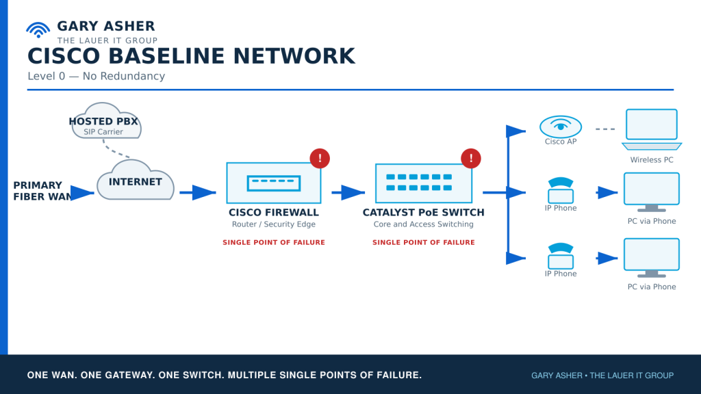
The Baseline Network: No Redundancy
A typical small healthcare location may begin with a straightforward network:
- One fiber or coax internet connection
- One carrier entrance into the building
- One firewall or gateway
- One core switch
- One uplink from each IDF to the MDF
- One access or PoE switch serving each work area
- One electrical circuit and one UPS—or no UPS
- One domain controller, DNS server, or DHCP source
- One hosted or on-premises phone system
- Phones powered by one PoE switch
- PCs connected through one wired network path
- Cloud applications dependent on one internet circuit
This design may be inexpensive and easy to understand, but nearly every major component is a single point of failure. A fiber cut can interrupt cloud applications and hosted phones. A failed firewall can take down both internet and site-to-site VPN connectivity. A failed core switch can isolate every closet. A failed UPS can disconnect phones, access points, and computers even when the carrier service remains operational.
A baseline design is not automatically irresponsible. It may be appropriate when downtime is tolerable, replacement equipment is readily available, and recovery procedures are documented. The important issue is whether leadership understands the exposure and has consciously accepted it.
Network Drawing 1 — Baseline Network: The first drawing in this series will show the internet carrier, firewall, MDF, IDF, core and access switches, wireless access points, PCs, phones, domain services, cloud applications, and hosted PBX. Red markers will identify every single point of failure.
The Physical Foundation: Cabling, MDFs, and IDFs
Network redundancy begins with the building. Redundant electronics cannot overcome a damaged cable, an overheated closet, an unsecured rack, or a fiber pathway shared by every uplink.
The Main Distribution Frame
The MDF normally contains the internet carrier handoffs, firewalls, core switches, servers, telephone equipment, fiber connections to IDFs, UPS systems, and power-distribution equipment. Its design should consider:
- Rack space and future growth
- Electrical circuits, UPS capacity, and generator support
- Cooling, ventilation, temperature, and water exposure
- Physical access control
- Carrier demarcation and building entrance paths
- Cable management, labeling, grounding, and documentation
Intermediate Distribution Frames
An IDF may support PCs, printers, VoIP phones, wireless access points, cameras, medical devices, workstations, modalities, and building systems. Each closet should be evaluated for switch and PoE capacity, UPS runtime, fiber connectivity, spare rack space, cooling, physical security, and future growth.
A phone may have a redundant PBX and two internet services, but it will still fail if its cable, PoE switch, closet UPS, or only fiber uplink fails. The same principle applies to wireless access points and medical equipment.
Structured Cabling
The assessment should document copper-cabling type and condition, fiber type and available strands, patch panels, patch cables, labels, certification results, cable routes, conduit, abandoned wiring, and available capacity. Updated as-built drawings are just as important as the physical installation.
Spare fiber strands can protect against a failed optic or individual strand. They do not protect against the entire cable being cut. Two uplinks in the same fiber bundle or conduit share a physical failure point. Two switches powered by one UPS share a power failure point. Two domain controllers on one virtualization host share a compute, storage, network, and power failure point.
Gary’s Cost-Saving Note: Test and certify existing cabling before replacing it. Use serviceable fiber strands and pathways where appropriate, but clearly document which failures they protect against. During planned construction, installing additional fiber capacity is often less disruptive than returning later.
The Network Redundancy Ladder
Redundancy does not have to be an all-or-nothing decision. A practical design can be built in levels.
Level 0 — Baseline
The network uses single components and single paths. Recovery depends on troubleshooting, replacement equipment, and available support. This level has the lowest initial cost and the greatest exposure to extended downtime.
Level 1 — Protection and Recoverability
The organization adds UPS protection, monitoring, configuration backups, secure credential storage, warranty coverage, documented recovery procedures, and strategically selected spare equipment. Most failures still require manual intervention, but recovery becomes faster and more predictable.
Level 2 — Practical Failover
The design adds a secondary internet connection, automatic WAN failover, secondary DNS and DHCP capabilities, another domain controller where required, mobile and desktop phone applications, and redundant closet uplinks where the risk justifies them.
Level 3 — Infrastructure Redundancy
The organization introduces high-availability gateways, dual core switching, diverse uplinks, greater PoE resiliency, redundant power, carrier-level telephone continuity, improved support coverage, and formal monitoring and alerting.
Level 4 — Business Continuity
The design protects against broader site and carrier failures with physically diverse WAN paths, cellular or fixed-wireless connectivity, generator-supported network infrastructure, alternate operating locations, secondary-site or cloud services, formal downtime procedures, and scheduled failover testing.
Not every component needs the same level. A healthcare organization might choose Level 3 protection for phones, internet, and core switching while using Level 1 recoverability for a noncritical administrative closet.
Primary WAN: Business Fiber
For this series, the primary design begins with fiber supporting normal operations. That may include medical imaging and DICOM transfers, cloud applications, VoIP, VPNs, remote support, backups, and general business traffic.
The word fiber does not describe a single service level. Shared broadband fiber and a dedicated enterprise circuit may have different capacity guarantees, repair commitments, support procedures, and escalation options. Those operational differences should be evaluated along with the advertised speed.
Redundant WAN: Coax Versus 5G
Once fiber is selected as the primary WAN, many organizations compare coax and 5G for the backup connection. The decision is not simply wired versus wireless. It is a choice between sustained capacity, path diversity, predictability, installation requirements, and recurring commitment.
| Consideration | Coax backup | 5G backup |
|---|---|---|
| Physical connection | Wired | Wireless |
| Path diversity | Depends on outside plant and building entrance | Usually independent of the wired building entrance |
| Sustained capacity | Generally better for prolonged outages | Varies with signal, congestion, and service plan |
| Latency and jitter | Usually more consistent | May fluctuate |
| Voice suitability | Generally strong when properly configured | Must be tested under real conditions |
| Large imaging transfers | More practical | May need to be limited or queued |
| Installation | Requires carrier installation and cabling | Often faster to deploy |
| Protection from building cable cuts | Only when physically diverse | Provides a different physical medium |
| Inbound connectivity | Depends on the service | May be restricted by carrier addressing or NAT |
| Portability | Fixed to the location | May be relocatable |
Fiber With Coax Backup
Coax is often the stronger choice when the organization needs to maintain near-normal operations during a prolonged fiber outage. It usually offers more predictable sustained capacity for cloud services, phones, VPNs, and larger imaging transfers.
The limitation is physical diversity. Fiber and coax from different companies may still share a pole, conduit, handhole, building entrance, upstream transport facility, or regional event. The organization should ask each carrier how the service enters the building and where practical shared dependencies exist.
Fiber With 5G Backup
5G can provide a physically different backup path without requiring another wired entrance. It may be especially useful during a construction cut or local wired-carrier failure. It can be an effective lower-cost continuity option for phones, scheduling, email, secure remote access, and essential cloud applications.
Its performance depends on signal strength, building construction, antenna placement, tower congestion, carrier backhaul, data-plan terms, and network addressing. Voice quality, VPN behavior, and application access must be tested. Large DICOM transfers, backups, synchronization, and updates may need to be limited while the 5G connection is active.
Fiber, Coax, and 5G
A location with very low tolerance for downtime may use fiber as the primary connection, coax for sustained secondary capacity, and 5G as a physically different tertiary path. This protects against more failure scenarios, but it adds equipment, subscriptions, monitoring, configuration, support responsibilities, and testing.
Gary’s Cost-Saving Note: The backup connection may not need the same bandwidth as the primary circuit. A lower-capacity coax or 5G service can protect essential operations if the firewall automatically restricts guest Wi-Fi, streaming, updates, large backups, and other noncritical traffic during failover.
Traffic Priorities During a WAN Failure
When the backup circuit has less capacity, the firewall should prioritize essential services:
- VoIP, SIP, and necessary PBX connectivity
- EHR and scheduling applications
- Required clinical communications
- Secure remote access
- Essential cloud services
- Limited critical medical imaging traffic
Guest Wi-Fi, streaming, routine cloud backups, operating-system updates, large downloads, and nonessential file synchronization may be temporarily restricted.
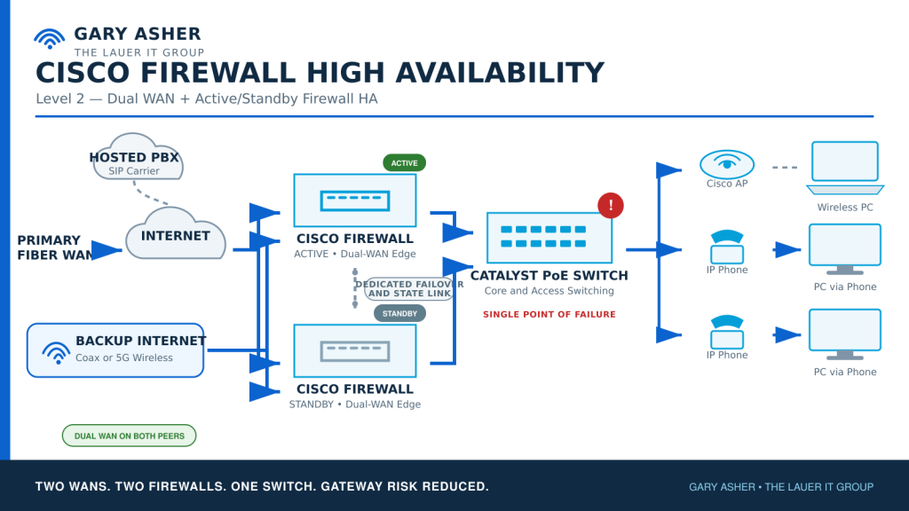
Network Drawing 2 — Dual-WAN Design: This drawing will show primary fiber, secondary coax or 5G, automatic firewall failover, the hosted PBX and cloud paths, and policies that distinguish critical from noncritical traffic.
Firewall and Gateway Redundancy
Dual internet still depends on the device connecting both services to the network. There are three common approaches:
- One gateway with configuration backups: Lowest cost, but recovery requires replacement equipment and manual work.
- One active gateway with a configured spare: Faster recovery, but someone must install or activate the spare.
- A high-availability gateway pair: Provides automatic or near-automatic failover when properly designed and tested, but increases hardware, licensing, support, and operational complexity.
A configured spare provides recoverability, not high availability. An HA pair may protect against gateway failure but still share one switch, one UPS, one rack, one electrical circuit, or one carrier handoff. The entire dependency chain must be examined.
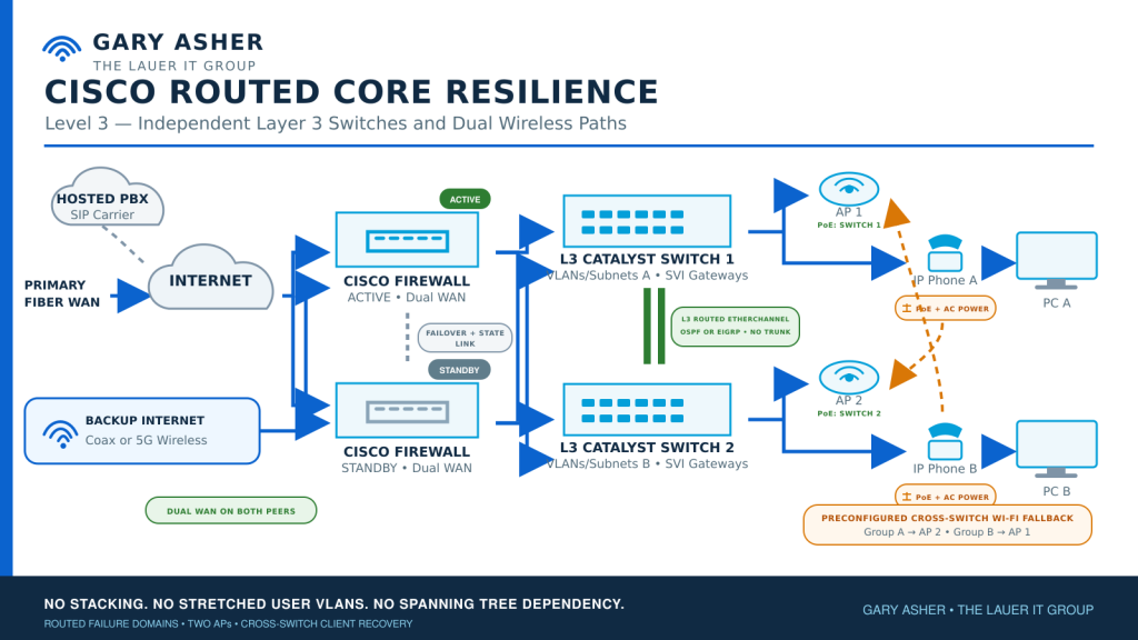
Core Switching and Closet-to-Core Redundancy
The path between the MDF and each IDF is critical because it carries traffic for PCs, phones, access points, cameras, and medical equipment. Redundancy options include:
- A documented spare switch and transceivers
- Two uplinks to one core switch
- Two uplinks to separate core switches
- Switch stacking or other multi-switch designs
- Link aggregation where it is appropriate
- Physically diverse fiber paths
- Sufficient PoE capacity after a switch or power-supply failure
Two uplinks to one core can protect against a failed port or optic, but they do not protect against failure of that core. Two links through one fiber cable do not protect against a cable cut. A design that looks redundant on a logical diagram may still have one physical failure point.
Loop prevention, link behavior, switch convergence, and recovery after the failed component returns must all be understood. Redundancy should not introduce instability that is more disruptive than the failure it was intended to address.
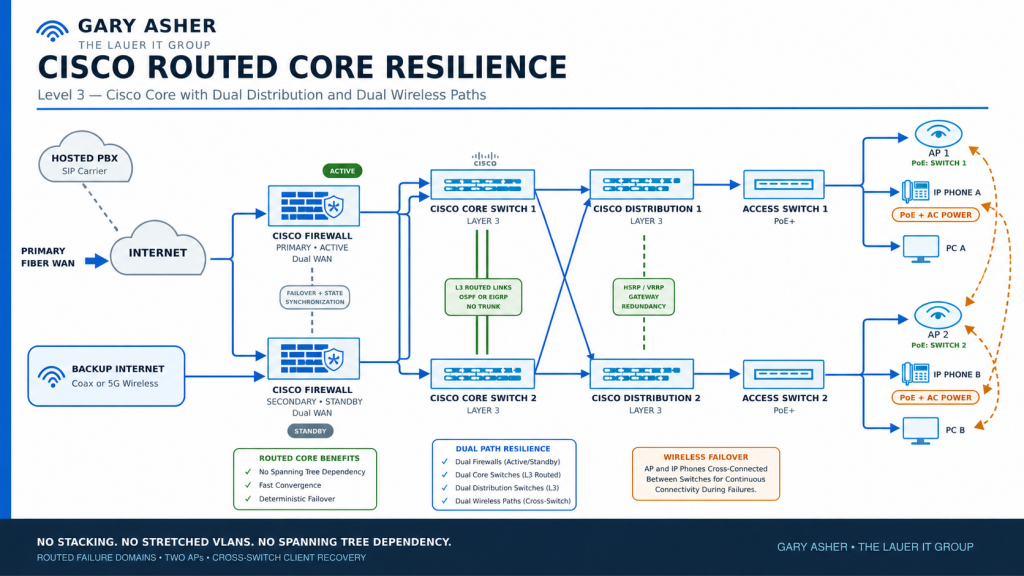
Network Drawing 3 — Redundant MDF-to-IDF Design: This drawing will show dual core switches, multiple IDFs, primary and backup fiber paths, and the connections supporting phones, access points, PCs, and medical equipment.
Wireless and Endpoint Continuity
Wireless redundancy is more than adding extra access points. Coverage, capacity, controller dependencies, switch placement, PoE, channel planning, and the path back to the core all matter.
Critical areas should have overlapping coverage where practical, and adjacent access points should not all depend on the same switch when a switch failure would isolate the entire area. Secure staff, medical-device, and guest networks should remain appropriately separated during both normal and backup operation.
A desktop PC with a wireless adapter has another way to reach the network if its Ethernet cable or switch port fails. It does not have meaningful site-level redundancy when Ethernet and Wi-Fi use the same access switch, core, firewall, power, and internet circuit. A laptop with cellular access or a separately connected hotspot provides a more independent path, but it introduces security, management, and application-access considerations.
Telephone and Communications Continuity
Healthcare network planning must include the complete voice path:
Desk phone → cabling → PoE switch → voice VLAN → DHCP, DNS, and NTP → firewall → internet → SBC or hosted PBX → SIP carrier → telephone network
A failure anywhere along that path can interrupt calling. Practical protections include UPS power, spare phones and PoE injectors, dual internet, desktop and mobile applications, carrier-level call forwarding, alternate answering locations, an SBC recovery plan, secure storage of carrier and PBX credentials, and accurate E911 information.
WAN failover does not guarantee that an active call will survive. The public IP address may change, SIP registrations may need to re-establish, and active media sessions may disconnect. The PBX, SBC, firewall, carrier, inbound calls, outbound calls, voice quality, and E911 operation must be tested together.
Where Not to Cut Costs: Emergency calling, E911 location information, unsupported voice equipment, and undocumented carrier recovery procedures should not be treated as optional. Analog devices, alarms, elevators, and fax requirements should also be identified separately rather than assumed to behave like ordinary VoIP phones.
DNS, DHCP, Domain Controllers, and Identity
A healthy internet circuit does not help users who cannot obtain an address, resolve a name, authenticate, or locate a required service. Core network services must be included in the redundancy design.
- DHCP: Determine where address leases are issued and what happens when that system becomes unavailable.
- DNS: Provide appropriate internal and external name-resolution paths and document their dependencies.
- Domain controllers and identity: Evaluate authentication, policy processing, and access to local resources during server or WAN failures.
- Time synchronization: Confirm that phones, servers, authentication systems, and logs maintain reliable time.
- Cloud identity: Determine whether cached access or emergency administrative procedures are available during an internet outage.
Two domain controllers on the same physical host are not fully redundant. They still share the host, storage, switch, UPS, rack, and building. The second service should be placed on an appropriately separate failure domain whenever the operational requirement justifies it.
Cloud-Based Applications and Services
Cloud services reduce some local infrastructure requirements, but they increase dependence on connectivity, identity, DNS, vendor availability, and subscription status. The assessment should ask:
- What continues working when the internet is unavailable?
- Can users authenticate with cached credentials?
- Can another location access the same application?
- Are local workflows available during a vendor outage?
- Does the cloud provider maintain or access ePHI, and are appropriate agreements and safeguards in place?
- How are data exported, backed up, and recovered?
- Which services require inbound connectivity, fixed addressing, or VPN tunnels?
Cloud management, cloud hosting, and cloud authentication are different dependencies. A cloud-managed network may continue forwarding local traffic when its management portal is unavailable. A cloud-hosted application may be inaccessible even though the local network is functioning normally. Each dependency must be documented and tested.
Power, Cooling, and Environmental Protection
A UPS provides temporary runtime, but one UPS remains a single point of failure. Power planning should consider:
- Measured load and required runtime
- UPS capacity and battery condition
- Battery replacement schedules
- Redundant power supplies
- Separate electrical circuits
- Generator-supported circuits
- Power-distribution units
- Cooling and ventilation
- Temperature, water, and environmental monitoring
- Alerts that reach someone able to respond
Gary’s Cost-Saving Note: Measure the actual equipment load before purchasing oversized UPS systems. Standardize models where practical, maintain a battery-replacement schedule, and use generator-supported circuits that already exist before adding unnecessary electrical infrastructure.
Support, Warranties, and the Full Cost of Redundancy
The cost of redundancy includes more than hardware. Every design should identify the commitments required to purchase, operate, renew, support, document, and test it throughout its life.
- Network, server, wireless, cellular, and voice hardware
- Primary and backup internet services
- SIP trunks, PBX services, and telephone numbers
- Licensing, subscriptions, security services, and cloud management
- Manufacturer, carrier, managed IT, and after-hours support
- Standard warranties, extended warranties, and advance replacement
- Locally stocked spare equipment
- Cabling, fiber, construction, electrical, cooling, and installation labor
- Monitoring, documentation, training, and scheduled testing
- Battery replacement, firmware maintenance, renewals, and hardware refresh
| Cost area | Baseline | Practical redundancy | High availability |
|---|---|---|---|
| Hardware | Lowest commitment | Additional circuits, spares, and selected redundancy | Multiple active systems and failure domains |
| Recurring services | Primary carrier and basic services | Backup carrier and added support | Diverse services and priority support |
| Warranty strategy | Standard coverage | Extended coverage or local spares | Advance replacement plus strategic spares |
| Recovery labor | Highest during a failure | Reduced through preparation | Lowest immediate interruption, higher ongoing administration |
| Documentation and testing | Basic | Detailed and scheduled | Formal, recurring, and comprehensive |
| Downtime exposure | Highest | Reduced | Lowest practical exposure |
Practical Ways to Control Cost
- Protect the systems most likely to interrupt patient care and operations first.
- Use a lower-capacity secondary circuit when essential traffic can be prioritized.
- Keep a configured spare where automatic failover is unnecessary.
- Standardize switch, access point, UPS, phone, and optic models to reduce the spare inventory.
- Test existing cabling before replacing it.
- Install additional fiber capacity during planned construction.
- Use mobile and desktop phone applications for temporary continuity.
- Purchase enhanced support for core equipment before extending it to every access device.
- Compare advance replacement coverage with the cost and recovery speed of a local spare.
- Coordinate licensing, warranty, and support renewal dates.
- Build the redundancy plan in phases rather than attempting to implement every level at once.
Cost control should not create a false sense of protection. Unsupported security equipment, inaccurate E911 information, untested backups, missing documentation, inadequate PoE capacity, weak closet security, or expired support can turn an inexpensive design into an expensive outage.
Common Examples of False Redundancy
- Two internet services using the same building entrance or outside path
- Two uplinks running through one fiber cable or conduit
- Two core switches connected to one UPS or electrical circuit
- Two domain controllers running on one virtualization host
- Multiple access points powered by one PoE switch
- A wireless-equipped PC using the same network infrastructure as its wired connection
- Configuration backups stored only on the device being protected
- A spare firewall with no current configuration or tested replacement procedure
- A secondary WAN that has never been tested with phones, VPNs, and critical applications
- Redundant equipment without monitoring, documentation, or available support
Monitoring, Documentation, and Testing
Redundancy that is not monitored can fail silently. Redundancy that is not documented may be impossible to support. Redundancy that is not tested may behave differently from the design.
A complete operational package should include:
- Current logical and physical network diagrams
- MDF, IDF, cabling, fiber, and carrier-path documentation
- Equipment inventory, serial numbers, support status, and lifecycle dates
- Configuration backups stored separately from the protected equipment
- Passwords, recovery codes, service accounts, and carrier credentials stored in an approved secure vault
- ISP, PBX, SIP, vendor, and escalation contacts
- Monitoring and alerting for circuits, gateways, switches, access points, UPS systems, and critical services
- Documented failover and failback procedures
- Scheduled testing with recorded results and corrective actions
Testing should include more than pulling the primary internet cable. It should evaluate gateway failure, switch and uplink failure, DNS and DHCP availability, phone registration, inbound and outbound calling, voice quality, VPN behavior, cloud access, 5G signal under load, recovery of the primary circuit, and correct return to normal routing.
Network Drawing 4 — Failure and Traffic Rerouting: The final drawing will show a failed primary fiber circuit or core component, the active backup path, restricted nonessential traffic, and continued connectivity for phones and critical applications.
Choosing the Appropriate Level
The appropriate design should reflect the number of users and locations, patient-care impact, phone dependence, cloud dependence, medical imaging requirements, acceptable downtime, internal support resources, after-hours needs, and recurring budget.
A smaller site may choose fiber, 5G backup, UPS protection, documented spares, and mobile phone applications. A larger imaging center may justify fiber plus coax, tertiary 5G, high-availability gateways, dual core switching, diverse closet uplinks, redundant domain services, generator support, and carrier-level voice continuity.
The best network is not necessarily the one with the most redundant equipment. It is the one that protects the organization’s most important operations, can be supported within its budget, and has been documented and tested before a failure occurs.
Coming Next in the Series
- Part 2: Designing a Redundant Healthcare Network with Cisco
- Part 3: Designing a Redundant Healthcare Network with Cisco Meraki
- Part 4: Designing a Redundant Healthcare Network with UniFi
Each article will apply the same baseline, redundancy ladder, cost categories, physical-path analysis, voice requirements, and testing standards to the specific platform.
About Gary Asher
Gary Asher works with organizations to design, document, troubleshoot, and improve networks, communications systems, and healthcare technology environments. His approach focuses on practical solutions that support operations without adding unnecessary complexity.
The Lauer IT Group