
Designing Resilient Healthcare Networks — Part 2
A practical Cisco design that progresses from a single firewall and switch to dual internet, active/standby firewalls, independent Layer 3 switching, and wireless recovery paths for phones and computers.
Cisco networks are often described as reliable because the equipment is proven and widely supported. That reputation is valuable, but no product eliminates the need for sound architecture. A dependable firewall can still fail. A Catalyst switch can lose power. A carrier can experience an outage. A software upgrade can create an unexpected problem. A phone can remain powered but lose its path to the hosted PBX.
Resilience comes from identifying those dependencies and deciding how much protection the organization actually needs. The right answer is rarely “duplicate everything.” A practical design adds protection in stages, documents what each stage accomplishes, and tests whether the intended recovery behavior works in the real environment.
This article follows four Cisco network levels. The drawings use a hosted PBX, IP phones, wired computers, wireless access points, dual internet services, Cisco firewalls, and Catalyst switches. The same principles can apply outside healthcare, but healthcare environments make availability, documentation, secure access, and operational recovery especially important.
How to Read This Article: Some elements are field-proven, some are documented Cisco capabilities, and some endpoint behaviors still require laboratory validation. The article identifies those differences rather than presenting an untested assumption as a guaranteed result.
Level 0 — The Cisco Baseline Network
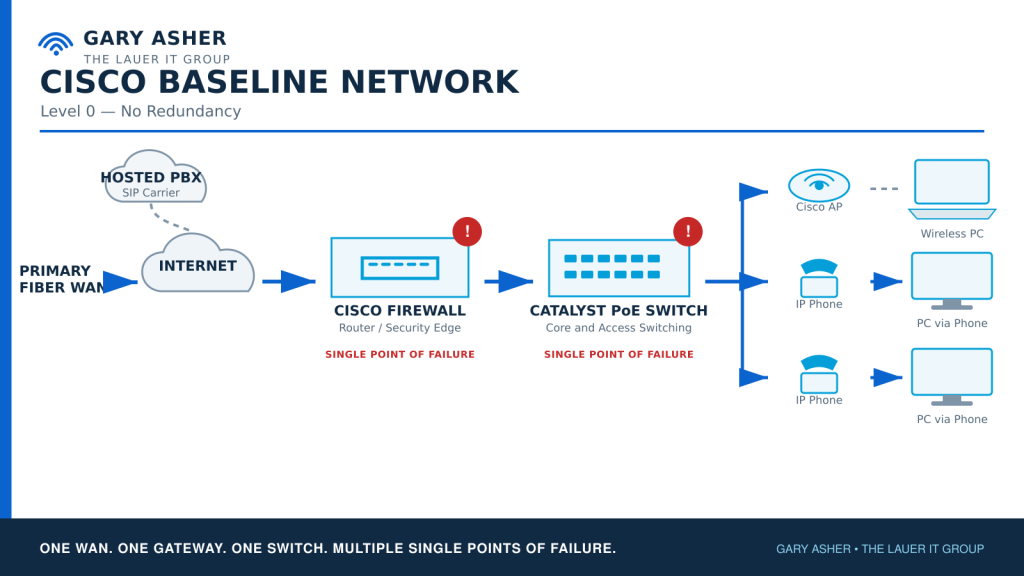
The baseline design represents a common small-business or branch-office network:
- One primary internet connection
- One Cisco firewall or security gateway
- One Catalyst PoE switch
- One wireless access point
- IP phones connected to the switch
- Computers connected through the phones
- A hosted PBX or SIP carrier
- One set of power, cabling, DHCP, DNS, and routing dependencies
This design is economical and understandable. It may be appropriate for a location that can tolerate downtime and has documented replacement procedures. However, the firewall and switch are obvious single points of failure. The internet circuit, UPS, carrier handoff, structured cabling, and hosted-voice path may also be single points.
The baseline should not be judged only by its purchase price. The organization should also consider the cost of downtime, emergency replacement, after-hours labor, expedited shipping, lost calls, delayed appointments, and reduced staff productivity.
Level 1 — Dual Internet With IP SLA and Tracked Routes
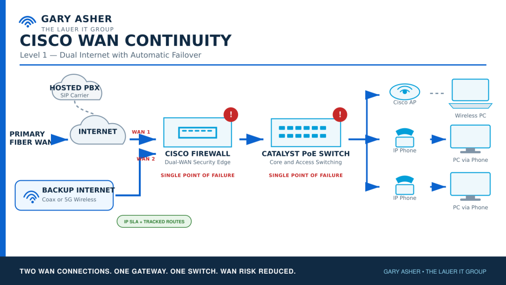
The first meaningful improvement is often a second internet service. In this series, the normal path is business fiber and the backup path is coax or 5G wireless. Using different delivery technologies can reduce the chance that both services fail from the same carrier or physical event.
A Cisco ASA can use IP SLA monitoring and a tracked primary route to detect a failure. The firewall periodically tests a selected destination through the primary connection. If that target becomes unreachable, the tracked primary route is removed and a higher-distance backup route becomes active. When the primary path returns, the preferred route is restored.
Cisco documents this design as static-route tracking for redundant or backup ISP links. The monitored target must be chosen carefully. Testing only the local carrier modem may show the circuit as available even when the carrier cannot reach the internet. Testing an unreliable or overly distant target can create unnecessary failovers. NAT, VPNs, hosted services, inbound access, DNS behavior, monitoring, and failback must all be reviewed for both WAN paths.
Cisco reference: Configure the ASA for Redundant or Backup ISP Links.
From the Field: Cisco ASA WAN Failover
While supporting a national glass company headquartered in Atlanta, I configured a Cisco ASA with a primary coax internet connection and a wireless backup service. IP SLA monitored reachability through the primary circuit. If the test failed, the ASA removed the tracked primary route and activated a higher-distance route through the wireless connection. When primary service recovered, traffic returned to the preferred route.
This provided practical WAN continuity without requiring a second firewall. It reduced carrier risk, but the ASA and downstream switch remained single points of failure.
When BGP Becomes Appropriate
BGP may be appropriate when an organization has its own autonomous system number, provider-independent address space, ISP cooperation, and a business requirement to advertise the same public networks through multiple carriers. It offers more control over inbound and outbound routing, but it also adds design, operational, monitoring, and support complexity.
For many small and midsize organizations, IP SLA with tracked routes is the more practical solution. BGP should be selected because the technical and business requirements justify it—not because it sounds more advanced.
Level 2 — Active/Standby Firewall High Availability
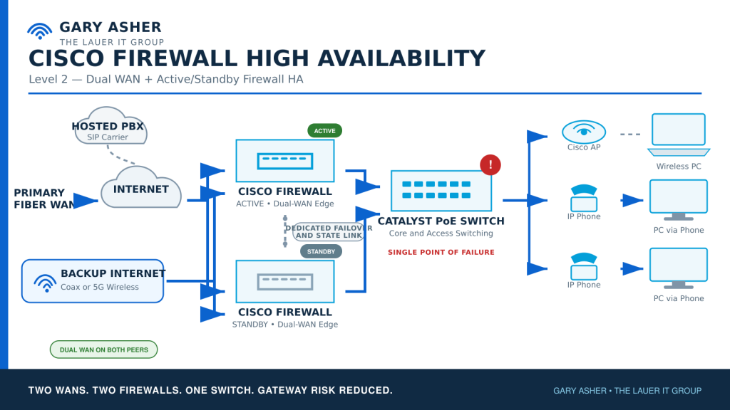
Dual internet protects against a carrier failure. It does not protect against firewall hardware, software, power, interface, or upgrade failure. Level 2 adds a second matching firewall in an active/standby high-availability pair.
- The active firewall normally passes traffic.
- The standby firewall synchronizes configuration and supported state information.
- A dedicated failover link monitors peer health.
- A state link preserves supported connection information during failover.
- Both WAN services must be available to both firewall peers.
- Both firewalls must have appropriate LAN connectivity.
- Power, licensing, software compatibility, configuration synchronization, and support coverage must be documented.
Cisco ASA and Cisco Secure Firewall platforms support high-availability designs, but requirements differ by model, software release, management platform, licensing, interface type, and operating mode. The final implementation must use the documentation for the exact hardware and software selected.
Cisco references: Cisco ASA Failover for High Availability and Cisco Secure Firewall High Availability.
The WAN Handoff Is Part of the Design
Both firewalls must be able to reach both ISP handoffs. Depending on the carrier equipment and addressing, this may require suitable carrier devices, dedicated WAN switches, separate handoff networks, or additional interfaces. Those supporting devices create their own power, cabling, monitoring, warranty, and failure considerations.
A pair of expensive firewalls does not create complete redundancy when both depend on one unprotected carrier modem, one small unmanaged switch, one outlet, or one patch cable.
Level 3 — Independent Layer 3 Core Switching
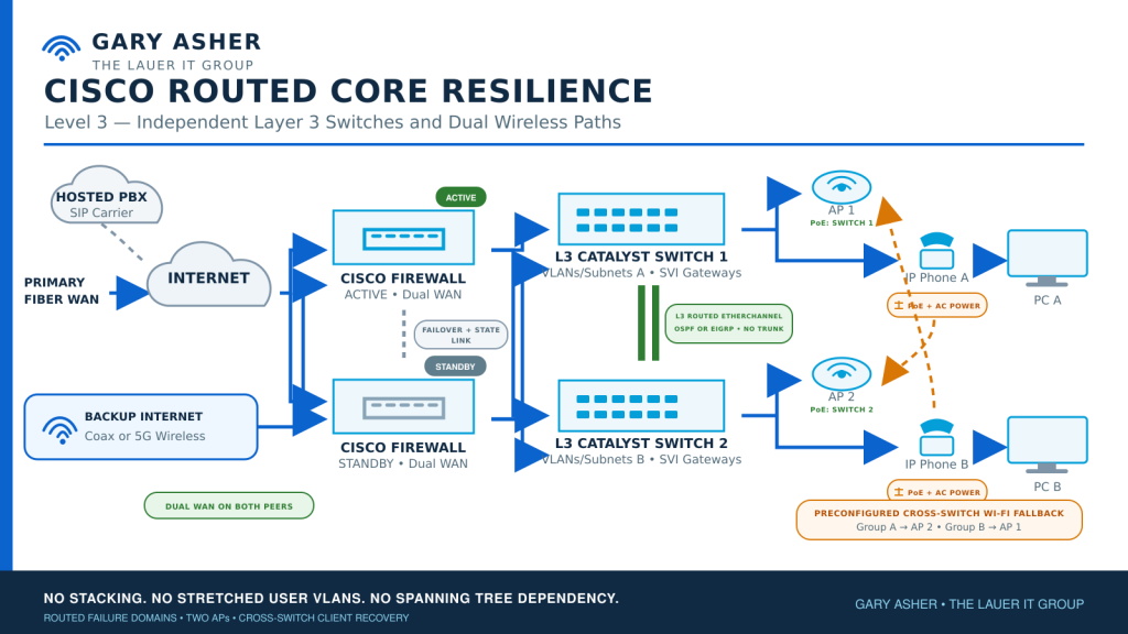
The next stage addresses the remaining Catalyst switch failure. This design intentionally uses two independent Layer 3 switches rather than a switch stack. Each switch owns its own user, voice, wireless, and infrastructure VLANs, IP networks, and SVI gateways.
- No stacking between the core switches
- No stretched user VLANs between the switches
- No Layer 2 trunk between the switches
- A routed Layer 3 EtherChannel between the switches
- OSPF or EIGRP for internal route exchange
- Routed transit connectivity between the firewall HA pair and both switches
- Independent failure domains for Switch 1 and Switch 2
- One PoE access point powered by each switch
The routed EtherChannel bundles multiple physical links into one Layer 3 path. The port channel uses an IP transit network rather than carrying user VLAN trunks. If a physical member fails, the remaining member can continue carrying routed traffic. If a complete switch fails, the routing protocol removes or stops advertising the affected networks.
OSPF or EIGRP
OSPF is an open-standard routing protocol and is generally easier to integrate when multiple manufacturers may participate. EIGRP is a reasonable option in a Cisco-focused environment where the support team already understands and standardizes on it.
The design should normally choose one internal routing protocol. Running OSPF and EIGRP together introduces route redistribution, filtering, administrative-distance decisions, troubleshooting complexity, and the possibility of routing loops. That complexity should exist only when a real migration or interoperability requirement justifies it.
No Spanning Tree Dependency Does Not Mean Disabling Spanning Tree
Because the inter-switch connection is routed, Spanning Tree does not select or block the core path. There is no stretched Layer 2 user domain between the switches. OSPF or EIGRP and the IP routing table provide convergence.
Spanning Tree should still remain available locally as protection against an accidental access-layer loop. Host-facing phone, PC, printer, and AP ports can use appropriate PortFast and BPDU Guard settings. Cisco recommends using PortFast and BPDU Guard together on host-facing access ports.
Cisco reference: Understand Spanning Tree PortFast and BPDU Guard Features.
Insert Drawing: Cisco Routed Core Resilience — Level 3, Independent Layer 3 Switches and Dual Wireless Paths.
Two Access Points and Cross-Switch Wireless Recovery
One AP cannot protect against either switch failing when the AP receives PoE from only one switch. The routed-core design therefore uses two access points:
- AP 1 receives PoE from Switch 1.
- AP 2 receives PoE from Switch 2.
- Phones and computers normally wired to Switch 1 are preconfigured to use AP 2 for continuity.
- Phones and computers normally wired to Switch 2 are preconfigured to use AP 1 for continuity.
- The AP coverage areas overlap sufficiently to support the opposite group.
- Each switch owns a separate continuity wireless subnet.
This is recovery across routed failure domains, not seamless Layer 2 roaming. A client moving to the opposite AP may receive a different IP address. Existing sessions may drop while DHCP, DNS, routing, application, and telephone registrations recover.
If Cisco controller-based APs are used, the selected wireless mode must continue forwarding the required traffic when the controller or original core path is unavailable. Cisco FlexConnect local switching is one example of a design in which locally switched clients may continue operating when controller connectivity is interrupted, subject to the exact authentication, VLAN, controller, and software requirements.
Cisco reference: Cisco Wireless Controller FlexConnect Configuration Guide.
Phone Power and Registration
A Wi-Fi-capable desk phone cannot use wireless after its PoE switch fails unless the phone still has power. The proposed design connects compatible AC adapters during normal operation in addition to PoE. At approximately $9 to $15 per adapter for the models discussed during design, this may be an inexpensive way to give each compatible phone an independent power source. The actual adapter must be manufacturer-approved or properly rated for voltage, amperage, connector, polarity, and safety requirements.
Phones wired to Switch 1 are preconfigured for the continuity SSID on AP 2. Phones wired to Switch 2 are preconfigured for AP 1. The opposite AP must have sufficient signal, an available voice-continuity subnet, DHCP, DNS, NTP, routing, and access to the appropriate 3CX services.
The protected SBC design should be reachable from every wired and continuity voice network. That may require routing, firewall-policy, DHCP, DNS, and provisioning changes across all phone subnets. A prepared spare SBC may provide faster recovery than relying on a complex clustering design that the organization does not routinely operate or test.
Lab Validation Pending: We still need to prove that the selected phones automatically move from wired Ethernet to their saved Wi-Fi profile, obtain an address on the continuity subnet, reach the protected SBC, re-register with 3CX, and return to Ethernet correctly when the failed switch recovers.
Computers Need Their Own Wireless Recovery Path
One potentially useful cost-saving option is allowing a computer connected to a desk phone’s PC port to share the phone’s Wi-Fi connection during an outage. We have not yet verified that behavior on the Fanvil X4U-V2. It may not be supported, may depend on firmware or configuration, and may cause both endpoints to depend on the same recovery process.
Until the phone-to-PC bridge behavior has been demonstrated, laptops should use their built-in wireless adapters and critical desktops should have approved USB or PCIe Wi-Fi adapters installed and preconfigured before an outage. Windows normally prefers wired Ethernet, but the continuity wireless profile provides another path when Ethernet drops.
Independent PC wireless also provides voice continuity when a desk phone does not re-register. The user can place and receive new calls through the 3CX desktop application over the surviving AP. The 3CX mobile application over Wi-Fi or cellular service provides another fallback.
- Primary: wired desk phone
- Secondary: desk phone through the opposite AP
- Additional fallback: 3CX desktop application over PC Wi-Fi
- Final user-level fallback: 3CX mobile application over Wi-Fi or cellular
An active call may be lost during the network transition. The continuity objective is to restore the ability to handle new calls and resume operations—not to promise that every existing session remains uninterrupted.
DHCP, DNS, Identity, and Cloud Dependencies
Redundant hardware is ineffective when the surviving network cannot issue addresses or resolve names. Every wired and wireless continuity subnet should be reviewed for:
- DHCP scope availability and DHCP relay configuration
- Default gateway and routing behavior
- Internal and external DNS availability
- NTP access for phones, network devices, authentication, and logging
- Domain-controller and identity-provider availability
- 3CX PBX, SBC, provisioning, and tunnel reachability
- Firewall policy, NAT, VPN, and application dependencies
- Cloud-management access for firewalls, switches, APs, and endpoint applications
If the continuity network depends on a DHCP or DNS server reachable only through the failed switch, users may associate with the surviving AP but still be unable to work. The design must protect the full service chain, not only the wireless signal.
What Still Requires Laboratory Validation
The network drawings represent a defensible architecture, but the following endpoint and application behaviors must be tested with the actual equipment, firmware, 3CX tenant, SBC, DHCP scopes, wireless profiles, and Windows configuration.
Fanvil X4U-V2 Wi-Fi and PC-Port Case Study
An AI-generated answer suggested that a Fanvil X4U-V2 connected through its optional Wi-Fi adapter could bridge that wireless connection to a computer attached to the phone’s physical PC port. It also supplied configuration parameter names. We could not confirm those claims in the official product documentation available during this review, so we are treating them as a hypothesis to test—not as a supported production capability.
Testing strategy:
- Record the Fanvil X4U-V2 hardware revision, firmware version, Wi-Fi adapter model, power adapter, 3CX version, provisioning method, SSID, VLAN, DHCP scope, and switch-port configuration.
- Export and securely retain the phone configuration before making changes.
- Power the phone with its approved AC adapter and connect it to the continuity Wi-Fi SSID.
- Connect a test computer to the phone’s PC port and confirm normal wired operation before introducing a failure.
- Disconnect the phone’s Ethernet network connection while leaving AC power connected.
- Observe whether the phone automatically joins Wi-Fi, receives the expected address, reaches the protected SBC, and re-registers with 3CX.
- Observe whether the computer retains an Ethernet link through the phone and receives a valid DHCP lease.
- Record the computer’s IP address, subnet, default gateway, DNS servers, DHCP server, and apparent VLAN or SSID network.
- Test gateway access, DNS resolution, internet access, approved internal resources, the 3CX desktop application, and any required business applications.
- Place test calls and verify inbound calling, outbound calling, two-way audio, DTMF, hold, transfer, voicemail, and call recovery.
- Restore the wired switch connection and record whether the phone and computer return to Ethernet automatically, how long recovery takes, and whether either device requires a new DHCP lease or manual intervention.
- Repeat the test after rebooting the phone and computer, then repeat it with relevant phone PC-port or VLAN settings enabled and disabled.
- Export the phone configuration after each controlled setting change and compare it with the original export to identify the actual provisioning parameters used by the tested firmware.
Evidence to retain: DHCP leases, packet captures where appropriate, phone and 3CX event logs, screenshots, configuration exports, firmware details, registration times, call-test results, failover and failback times, and any manual recovery steps.
Results: Testing has not yet been completed. This section will be updated with the observed behavior, limitations, configuration, and repeatable results. If the PC port successfully bridges the continuity Wi-Fi connection, we will document which network the computer uses and whether the behavior is reliable enough for production. If it does not, the independent computer Wi-Fi adapter remains the recommended recovery path.
Sources reviewed: Fanvil X4U official documentation, Fanvil X4U-V2 firmware downloads, and 3CX information identifying supported SBC-capable Fanvil phones. These sources establish available product documentation, firmware, and 3CX support context, but they did not confirm Wi-Fi pass-through from the phone to its PC port.
| Scenario | Expected Result | Validation Status |
|---|---|---|
| Complete failure of Switch 1 | Group A devices use AP 2 and the surviving routed network | Lab test required |
| Switch remains powered but loses routed uplinks | Devices detect unusable Ethernet and select wireless recovery | Lab test required |
| Desk phone loses PoE but retains AC power | Phone selects saved opposite-AP profile | Lab test required |
| Phone moves to continuity voice subnet | Phone receives DHCP, reaches SBC, and re-registers | Lab test required |
| Failed switch returns | Phone and PC prefer Ethernet, obtain the proper addresses, and recover cleanly | Lab test required |
| Fanvil X4U-V2 uses Wi-Fi with a PC connected behind it | Determine whether the PC port bridges Wi-Fi, which subnet the PC uses, and whether recovery and failback are reliable | Lab case study pending |
| PC has an independent wireless adapter | PC uses its own continuity profile if its wired path fails | Lab test required |
| Desk phone does not re-register | 3CX desktop and mobile applications handle new calls | Lab test required |
| Active firewall fails | Standby firewall becomes active and restores supported traffic | Implementation test required |
| Primary WAN fails | Tracked route or selected routing design moves traffic to backup service | Implementation test required |
The test plan should record registration time, DHCP time, DNS behavior, route convergence, call success, two-way audio, DTMF, hold, transfer, voicemail, application recovery, failback behavior, monitoring alerts, and relevant logs. Testing should include both controlled failures and restoration.
Power, Cabling, and Physical Diversity
Two firewalls and two switches still share risk when they use the same UPS, circuit, rack, cooling system, fiber bundle, or cable pathway. The physical design should consider:
- Separate UPS protection for the two switch paths
- Separate power supplies and circuits where practical
- Generator support for critical closets
- UPS runtime and battery-replacement schedules
- Diverse copper and fiber pathways
- Spare optics, patch cables, power supplies, and adapters
- Environmental monitoring for MDFs and IDFs
- Accurate rack, cable, port, VLAN, IP, routing, and power documentation
The two cross-switch APs should be placed so either one can provide usable emergency coverage to both device groups. A predictive design and site survey are more reliable than assuming the signal will reach after the failure occurs.
Cost Categories Beyond the Equipment
The design documents should not use one universal dollar estimate. Product models, licensing, carrier availability, cabling, building conditions, labor, and support requirements vary. The budget should include line items for:
- Primary and backup internet services
- Firewall hardware, subscriptions, licensing, and support
- Second firewall and HA-compatible interfaces
- Two Layer 3 PoE switches
- Wireless access points and management requirements
- Phone AC adapters and PC Wi-Fi adapters
- UPS systems, batteries, circuits, and power-distribution equipment
- Fiber, copper, optics, patch panels, and installation
- Configuration, migration, documentation, and testing labor
- Monitoring and alerting
- Manufacturer warranties and support contracts
- Carrier service-level commitments and escalation procedures
- Onsite spare equipment and secure configuration backups
- Recurring failover tests and documentation updates
Practical Ways to Control Cost
- Protect the workflows with the highest operational impact first.
- Use IP SLA and tracked routes when BGP is not justified.
- Certify and reuse serviceable cabling rather than replacing it automatically.
- Purchase appropriately sized equipment instead of selecting the largest available model.
- Use inexpensive AC adapters to preserve compatible desk-phone power.
- Install PC Wi-Fi adapters first on front-desk, scheduling, clinical, management, and other critical workstations.
- Keep tested spare optics, power supplies, adapters, patch cables, and a prepared replacement switch onsite.
- Standardize configurations, templates, labels, and documentation across locations.
- Use planned maintenance windows to test failover instead of waiting for a real emergency.
- Review warranty and support terms so redundant equipment can actually be repaired or replaced promptly.
Gary’s Practical Note: Redundancy that nobody understands, monitors, documents, or tests may fail when it is needed most. A simpler design with trained support, current diagrams, secure credentials, known spares, and scheduled validation is often more dependable than a complicated design that exists only on paper.
Implementation and Validation Checklist
- Document business and clinical recovery priorities.
- Inventory hardware, licenses, subscriptions, warranties, support contracts, power, cabling, carrier services, VLANs, IP networks, DHCP, DNS, and routing.
- Confirm firewall and switch model compatibility with the selected HA and routing designs.
- Confirm both WAN services can reach both firewall peers.
- Configure, monitor, and test primary and backup WAN behavior.
- Configure and test active/standby firewall failover.
- Configure independent Layer 3 switch networks.
- Select OSPF or EIGRP and document routing policy, metrics, summarization, authentication, and convergence expectations.
- Build and test the routed EtherChannel.
- Configure local access-port protections, including appropriate PortFast and BPDU Guard.
- Install one AP per switch and verify opposite-area coverage.
- Install and test approved phone AC adapters and PC Wi-Fi adapters.
- Configure cross-switch continuity profiles before deployment.
- Make the protected SBC reachable from every required voice network.
- Validate DHCP, DNS, NTP, identity, cloud, VPN, and application dependencies.
- Store credentials, recovery codes, configuration backups, support information, and license details in an approved secure credential vault.
- Record baseline and failover monitoring results.
- Publish an outage procedure for staff and technical support.
- Schedule periodic tests and update the documentation after every meaningful change.
Final Thought
A resilient Cisco network is not one product or configuration command. It is a set of coordinated decisions covering carriers, firewalls, routing, switching, wireless, phones, computers, power, cabling, DHCP, DNS, identity, cloud applications, support, spares, and testing.
The four levels in this article allow an organization to improve resilience without pretending that every business needs the same design. Dual WAN may be enough for one location. Another may justify active/standby firewalls and independent Layer 3 switches. The important questions are what the design protects, what risks remain, and whether recovery has been demonstrated.
The next articles in this series will apply the same practical framework to Cisco Meraki and UniFi environments, including their different approaches to management, failover, support, cost, and operational complexity.